It could be argued that the human body is the most complex machine ever known. After all, there are parts so complex that we are still trying to determine how all the pieces work together. The truly amazing part is it takes just 23 pair of chromosomes to make each of us unique.
PCB designs as much as they have changed in complexity have never veered in a direction where the fundamental build blocks really had to change. Terms such as pads, flash, vector, lines, traces, contours, areas, surfaces, islands, holes, arcs and text amongst other references are often not clear. Let’s take a closer dive into what makes each of these PCB designs different from the fundamental elements that make them what they are.

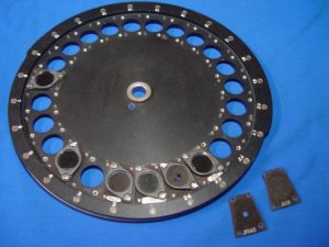
In the early days of the Gerber photo plotter there was a part in the machine called a wheel. The wheel had holes surrounding the circumference creating an aperture wheel. The apertures were of different shapes that when light passing through created different shapes of light. The different shapes also varied in size. When a piece of film was placed beneath the wheel and light was let to pass through the apertures, unique patterns could be made depicting the layers to be used in the PCB. These shapes in the apertures are today referred to as symbols and could be as simple as a round or square or more complex such as a diamond, octagon, oblong, rectangle, and many, many others. Today these symbols are far beyond the complexity of what an aperture could have ever depicted at the start, but the basic principle of different shapes of just about in an infinity number of sizes are the foundation of all PCB manufacturing.
Within ODB++D the most fundamental use of shapes is to create pads or lines. Some may refer to these as flashes for the pads or routes, vectors or traces for lines. A pad is the use of a symbol at a single location such as a round or rectangular pad. A line is a symbol that has a starting and ending point and thickness connecting the two points. An arc is closely related to a line with a start and end point but also a center used to define the radius to follow to connect the two points. Originally that was all that made up PCB layers and for the most part that is all that is used today.
With the original photo plotter, large solid regions were generated using an aperture and exposing the film in a pattern of overlapping series of lines. As these plotters began to be replaced with laser based systems, large drawn areas became a bottleneck in digital processing and contours or surfaces began to take form. In ODB++D these filled areas are referred to as surfaces. A surface consists of a filled island with the possibility of holes within the island. Holes represent voids in the area defined by the island. Since the number of holes is variable the term “an island with n-number of holes” may be used by a few.
So far for ODB++D there are pads, lines, arcs and surfaces. The last element is text which consist of a format defined font which describes how to create the typical character set. Most commonly, text on layers is made up of a series of non-design related lines, but ODB++D-defined text can also be found in title blocks such as when a production panel is being created.
Pads, lines, arcs, surfaces and text finish out the list of basic ODB++D layer elements. What makes some of them unique from the others is the symbol to be used while creating them. The one additional item they all do have is their polarity, positive or negative. You can think of polarity as if you took a piece of chalk and drew a series of horizontal or positive lines. Later you grabbed an eraser and with one vertical movement erased a portion of the lines creating a subtractive or negative action. This negative action however is remember as a line meaning that you can delete the negative line returning the completely untouched set of vertical positive lines. This make the negative action equivalent to the positive one only in a subtractive manner.
As unbelievable as it might seem, layers within PCBs today are created based on five primary building blocks some of which are created using a virtually-limitless set of symbols in two polarities. Yet that basic set of blocks has been used to create your car key fob, your cellphone, to put man on the moon, enable us to drive a rover on Mars and even reach beyond the outer edge of our known galaxy. It is amazing what a few simple block can do at times and with far less than 23.

